My kit did not have a tender hand pump handle, which is used to reach down to the hand pump through the water hatch and work the pump. I mentioned this to a guy I met and talked with a few times, as he himself has built two Mikados, and he whipped me up a very nice looking brass handle on his lathe and sent it to me. I got it today. I hope I can repay the favor one day. Thanks Charles.
Tuesday, May 31, 2011
Meeting good folks
In this hobby I have already met a lot of nice folks. People who are willing to help out a guy like me who is relatively new to live steam. I have learned a great deal over the past year by frequenting MLS.com, talking with people both via email and over the phone and seeing first hand live steam. Even smelling a coal fired live steamer thanks to Andrew.
Loose the Binding
That was my next project. I needed to be sure I had the correctly milled coupling rods as I was told by Jeff Runge that I needed to be sure there was no binding and he had to work through a similar issue with one he assembled. So, even though my intention was not to commence the chassis assembly, I wanted to check for my peace of mind.
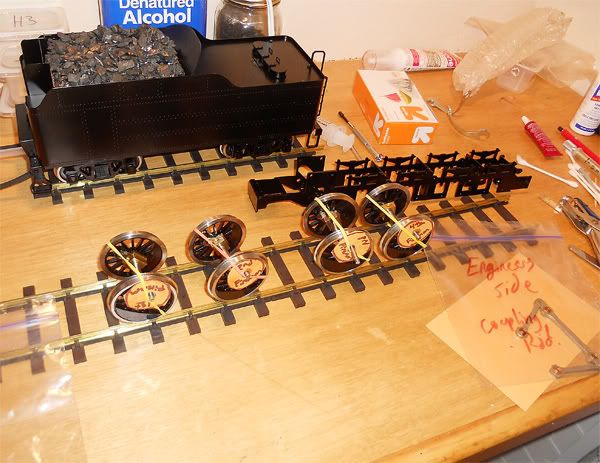
I put the Driver axles in the side frames and had to use a bit of oil to have them slide in a bit better. It is here where one must be careful to follow directions and diagrams to ensure the proper placement of the driving axles in their respective places in the side frame. Now was time to place the coupling rods on the drivers. Since this was only a "dry" run, I did not put the axle springs in or secure the rods with the hardware. However, I did make sure everything was where it would be had I done so.
Then I rolled it forward and it did move until a certain part where it would bind up. After consulting with people like David Leech, Jeff Runge and Hans, I was able to find the source of the binding. It was, to my relief, not the rods, but rather some tight fitting on the front most Driving axle. After some oil and some rolling back and fourth, coupled (no pun intended.....well perhaps just a little) with switching coupling rods to opposite sides, the chassis rolled very smoothly at just a touch of my finger. In both directions too. So, when I do assemble it later, I will file a bit of paint off of the frame where the axle will fit into. I carefully labeled the parts so when I put them back in the box and took them out later I would know the orientation that worked best.
Those cylinder studs won't be too much of an issue. I can always get some longer ones from Aster, or I could back out the threads a bit to give me more on top the valve covers which will allow for more threads to secure the retaining nut to.
Monday, May 30, 2011
Who needs a load of coal?
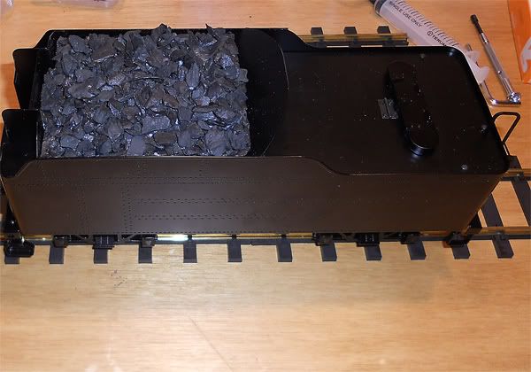
Well, I did and with some Aster kits, you need to make your own. I believe the Aster K4 had a dummy coal load provided, but making your own can be so much more gratifying. I have made them for coal hoppers on my 0 gauge set before, so I had some small sized pieces of coal. While the pieces will be a bit large for this model, but you can always break them down smaller, if it bothered you, by using a hammer. I think it still looks fine the size they are and besides, breaking it down can be messy and you have to have something to collect all those small pieces.
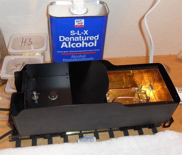
I had to decide which material to use for the bed which will be placed atop the fuel tank covering the needle valve and fuel filler cap. Be careful here when fitting things as there is a small breather tube near the needle valve which is uncovered. I placed a small piece of scotch tape over it during my fitting phase as I chose to use Styrofoam for both it's light weight and mold-ability. Remember to remove that tape after your fitting process if through.
I bought a small sheet of Styrofoam up at my local craft store. About 3/4 inch thick.
You may have something lying around from a shipping container, but I wanted something flat and also thin. I made a paper pattern which followed the contours and slop of the tender's coal bay. Then I traced the layout on the styrofoam board. You can either use a cutting device which is a heated wire for cutting (less mess, but more fumes) or you can use a hobby knife/box cutter. I had the latter so I carefully cut out the pattern. I then used a lighter to burn and also melt the small pieces of foam so it would not continue to shed each time it was moved. I also used the lighter to burn some dimples in the top of the load so it would not be perfectly flat when I applied my first layer of coal to it.
After checking the fit, I cut a small loop of thin and flexible wire to feed into the foam for a way to lift the coal load out of the tender when needed. Then I painted the whole piece with a matte black spray. After drying, I covered the bottom of the foam in clear packing tape. If the load were to ever break, it would not be in two pieces and it will stop any small pieces that might fall of the bottom from entering the breather tube.
Now it was time to glue on the first layer of coal. I was reminded by David Leech to not use a water soluble glue as being outside under rain could prove disastrous for your coal load. I chose a multipurpose glue for all weather conditions, or so it said on the bottle. I chose something which would dry clear as well, like Elmers does. It is called WELDBOND and is non-toxic.
After applying a layer of glue I sprinkled the coal down and allowed it to dry. When dry, you can turn the load upside down and the pieces that did not stick can be gathered up and used for the second layer which will add more realism to the coal. Now it is a matter of personal preference on how to continue to build the load of coal.
For now I am satisfied with my coal load and can always tweek it a bit if I so choose.
Sunday, May 29, 2011
Thanks
I would like to add, that the way I was able to obtain this Kit was through a selfless act of kindness on the part of the individual who sold it to me. The seller was not necessarily looking to sell, but rather gave up their own plans for the kit. Thanks. I wish all those who are in live steam could share the joy of building a kit and seeing it come to life. I have built many model kits as well as architectural models and they were fun, but in the end, they could only be set aside for decoration or dust collecting duties. This kit is something which I will be able to take pride and joy from and share it with my family. I work with children and I will be able to share this with them as well and introduce them to the hobby of live steam. If you are pondering what to get for your first engine, or perhaps your "next" engine, why not try a kit if you have never built one before. I would buy any kit, no matter the manufacturer, if it were of this quality again. I can highly recommend Aster. Not because of the name, but because of the experience.
I would also like to take this opportunity to thank the people that have been of much assistance over the course of the last year which has been my journey into learning about live steam. mls.com has a page on live steam, which is where I learned a lot. People like Charles, Ryan, Semper Vaporo(charles), Jeff, David, Art, Mike, Norm, Jim, Harlan, Hans, Will, Rob,Dan,Tac,Andrew and many more I have not mentioned have helped me learn the ropes of live steam. Thanks guys. I hope to meet those I have not yet at a steam up one day.
Details
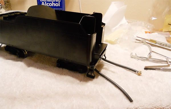
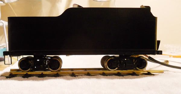
I added the detail parts to the tender which were the steps, ladder, rear coupler and front pin for coupling to the engine.
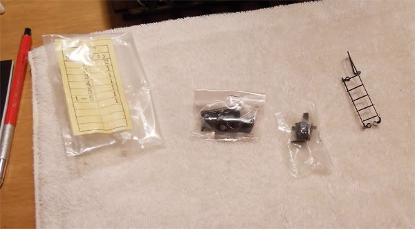
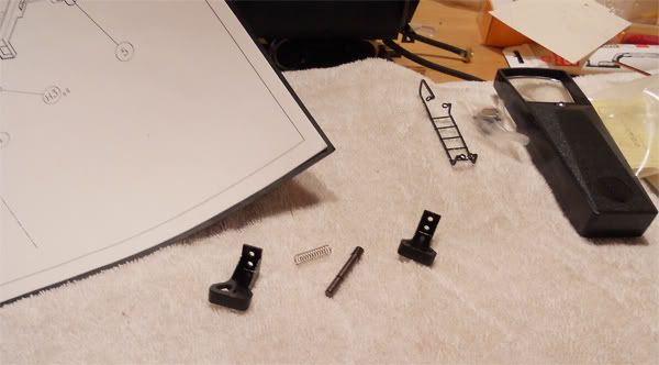
Some notes on the details. I experienced more trouble trying to get that collar on the pin after the spring and washer were on, then any other part of the kit this far. Not to be deterred, I took my time and used an allen wrench to push the collar onto the pin's slot. (My fingers were too sore from tying to push it on). It was interesting using one hand/screwdriver to hold down the washer and spring and the other to push on the collar. It helped that the pin was held in the hole by the fuel tube below it, but eventually I had to turn the tender upside down. Seemed to be easier that way. Having a white towel is great for both discouraging the bouncing/rolling of dropped hardware and creating a soft work surface to keep the kit from unnecessary abrasions.
I had to file a bit of the side (hidden behind the tender bottom edge) of one step to align with the threaded holes. Other than that, no big problems. Now it is time to make the dummy coal load.
Holds fuel and water with no leaks, the pump works smoothly (no pressure to over come in boiler at this point) and the fuel needle valve closes the flow of fuel properly.
I am trying to track done some "longer" cylinder studs as the ones supplied in my kit are too short. Aster should have some stock left of these parts. Good thing I won't be building till late summer anyway.
Saturday, May 28, 2011
Plumbing the Mikado's tender pump
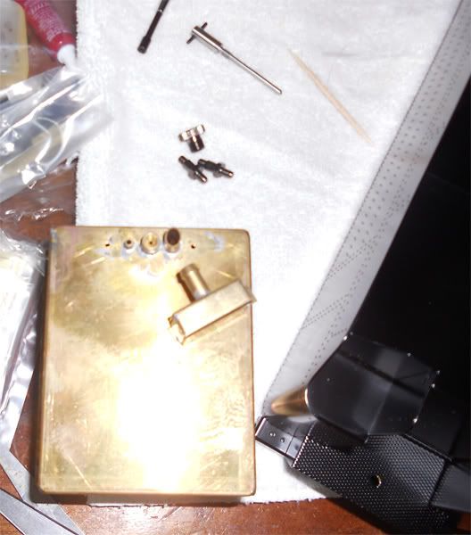
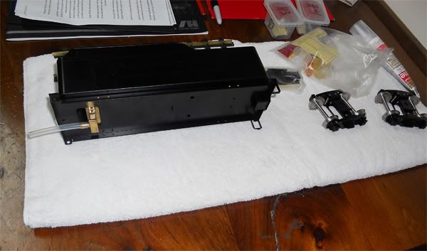
So, after seeing that the fuel tank was installed without issues, I decided to finish the tender by building and installing the tender pump. Here is another example that shows all one really needs other than the kit, instructions and tools is common sense. Where the instructions dictated one part number, my exploded diagram showed a different part number. Well, looking at the part and visualizing how it was going to work and how the drawings showed it assembled, I got er done.
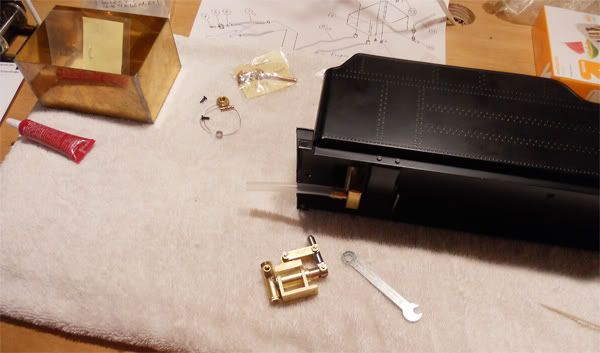
It was a joy seeing the final pump assembly after looking at all those parts and having the question in the back of my mind, "are all the parts here?", certainly gave me a bit of concern. My kit had the pump kits added after market and some were in bags written on by the dealer. I am still looking for the pump handle that the drawings show, but I have a replacement pump handle on the way, so no worries there.
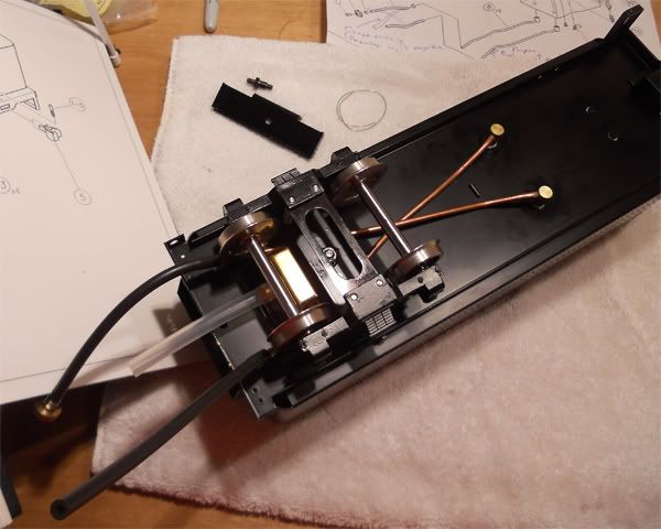
Now it was on to installing the copper pipes that will feed the boiler and allow the return water back into the tender when the bypass valve is open. The purpose of the tender pump is to inject water into the boiler both when starting up and under pressure. There are steel balls that act as clack valves which only allow water to be sent in one direction. This is at least the theory of how they work. Sometimes dirt and such can get in there and cause the functionality to change a bit. In writing this blog, it is the author's assumption that those reading it have a basic understanding of how the parts that make up a small scale live steam engine work. If you are interested in learning a lot more there is a good book I can recommend. A PASSION FOR STEAM by Marc Horovitz.
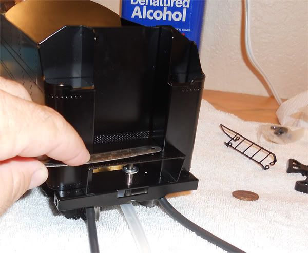
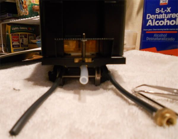
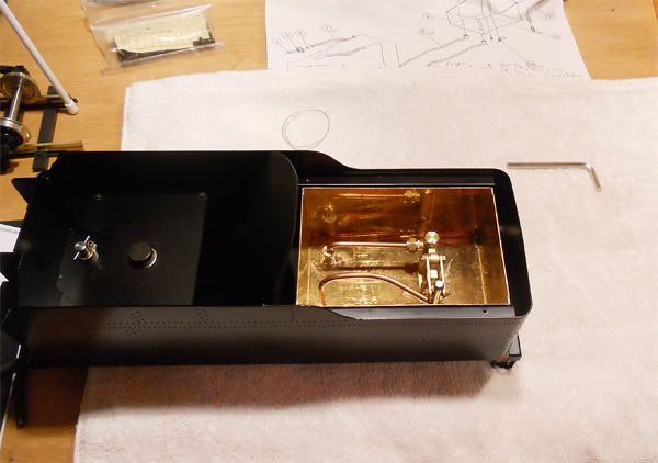
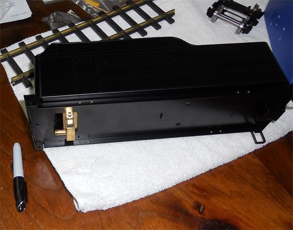
After seeing how I wanted to arrange the pipes, I mounted the pipes into their unions after applying some packing compound to give a good water tight seal between the tender and tender water receptacle which is made up of sheets of brass soldered together. There are holes where the water pipes from the water pump must connect with the copper lines underneath the tender, so you don't want all your water wasted because you didn't seal up the holes good.
I then mounted the tender hand pump and connected the lines inside the tender to the outside lines. I also had to bend a few small wrenches to better fit the unions in the tight corners. No, those aren't forged steel wrenches, they are thin steel ones. It sure beat going out to hunt down something which would work.
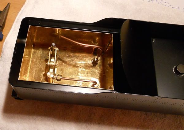
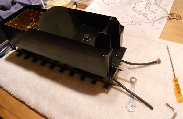
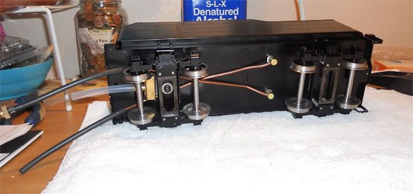
After assembling and installing the water lines and tender pump I put on the rubber hoses and attached the threaded fastener which will connect one of the lines to the boiler supply line that will be on the engine.
Next it was time to put those trucks I had assembled yesterday onto the tender. Everything went together a bit easier than I had expected, but I did have some moments where I had to stop and think how it would be best to do something. I am very pleased so far. Next I will add some detail parts to the tender and make a "dummy" coal load for aesthetic purposes when it graces my shelf between steam ups. There will be no storage box for this loco.
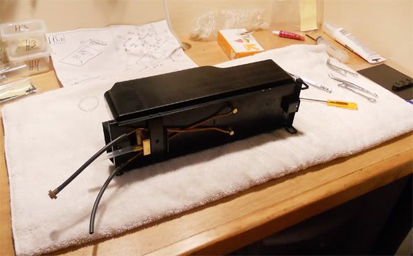
Tonight after the packing compound has dried, I'll do a water test to make sure I won't be wasting any water needlessly. I'll also give the pump a few strokes to test it as well. I will be taking a break for the summer vacation so I will not be working on the engine until I return later in July. I hope all who have read this have been both entertained and enlightened. I am really glad to have the chance to build this engine to both better understand it's workings and to have something which will last me to share the fun with my son and daughter.
Packing dried, so I tested it. No big leaks, but there was a droplet of water forming under one of the mounting screws of the pump, so I added a touch more caulk around that screw.
Friday, May 27, 2011
A turn of the screw
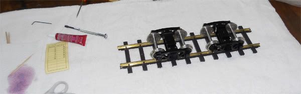
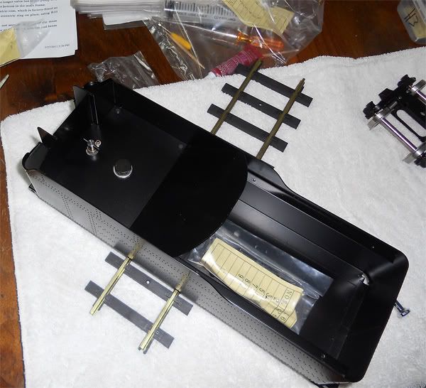
So, after not being able to contain my excitement or patience to wait, I decided I would at least get the tender assembled and the hand water pump installed. That way, I could set it atop my dresser and make a dummy coal load before I set off on my summer break. So, after making sure I understood the process involved in assembling the tender trucks, I set to it.
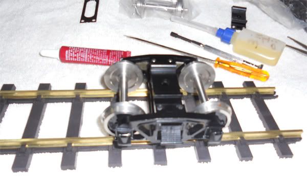
Common sense goes a long way in assembling this, just like building other kits and models. I was pretty active in building small scale castles and buildings out of blocks poured from molds I bought using Dental Plaster as the mix. So, building things is something I have always enjoyed doing. This Aster kit fits my building desires like a glove.
A little machine oil, some aid of the screwdriver and the first truck went together like a well oiled machine and ran smooth as butter on the track that Aster has you construct. Nice touch.
A while later and the second one was rolling just as smooth. Man, that seemed to go too fast and easy. I realize that there was not much involved with the two trucks other than gathering all the parts and doing the work.
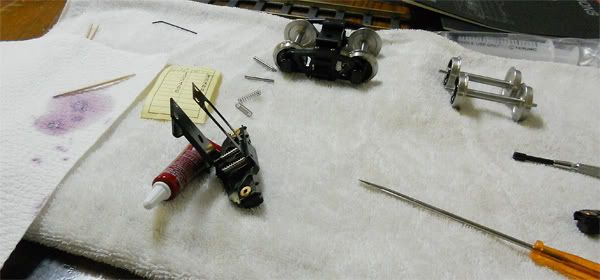
I took a break to eat some supper and get a tube of silicone bathroom caulk. Then it was time to install the fuel tank and sump. After gathering the appropriate hex bolts I would need, I poured out a bit of caulk on a napkin with toothpicks standing by. I took a Hex bolt and carefully applied a bit of the caulk onto the threads then placed it in the hex driver and carefully threaded it into the holes of the sump and tank. After a rinse/repeat, both bolts were snug as a bug in a rug.
Now, here I wondered if I had used enough caulk. Don't want any excess alcohol leaking out, but I can check that later after the caulk as cured.
Next it was onto installing the o-rings onto both the fuel cap and needle valve. Here is where some of the translation between directions and hardware packets may have stuttered a bit. After realizing the only 0 ring which seemed to match both the fuel cap and the directions was labeled PN-7, but the bag labeled it PN-7-1. Like I said, a bit of common sense helps and before I could say Yatzee, both 0-rings were on the caps and threaded into the fuel tank. A bit loose so as not to crush the 0 rings needlessly as the tank is still empty.
After this, I cleaned and closed up shop for the evening. Tomorrow, I'll put some fuel into the tank to ensure those two hex nuts hold their weight. Then it is a matter of assembling and installing the tender pump. I expect that this step will be a bit more involved, but I anticipate the challenges awaiting me.
After caulking had dried, I filled up the tender fuel tank with denatured alcohol using the syringe I got with the kit. I had the tender straddling a container should any leaks occur, but there were no leaks. The fuel came out the hose when the needle valve was opened as designed. I blocked off the tube and the chicken feed system worked again with no leaks out of the sump. I will put a very fine bead of caulk around where the sump sits flush against the bottom of the fuel tank for added measure.
tools of the trade
Reading the construction notes along with the diagrams show just how detailed this kit is, with all it's minute working parts. I had to have a feel for how the stock hex nut driver supplied with the kit would work. It is a 3mm hex nut driver and I noticed no burs or sharp edge on the end, so I did not have to file/sand anything (I was given the advice to look for such flaws which might scratch the paint when snugging down the nut/bolt). I took out the tender and simply removed the top which held the fuel tank in place to the body. Very smooth. I put it back on. I have a habit that I have picked up over the years of working with things to counter any potential of cross-threading a bolt or screw when working with fine threads. I make sure to align it properly (no side-angle entry) and turn counter-clockwise (lefty loosey) a turn or to, then clockwise (righty-tighty) and if it feels right, no resistance, I know I have it. Seems as though this will be of utmost importance when working with such small screws/nuts as they are going into brass.
I packaged it back up to build later.
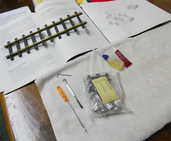
Kit Arrival
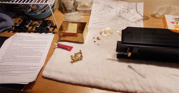
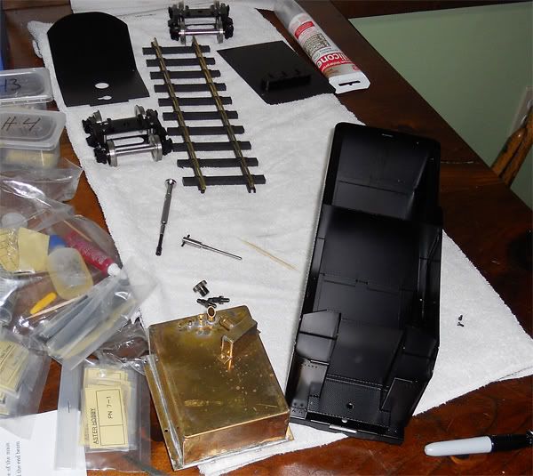
My Aster Mikado Kit has arrived at the construction facility. Construction of this USRA Light Mikado (black) will commence shortly. My intention with this blog will be to both show the progress of an Aster build as well as to create a nice place to show photos of this exciting journey.
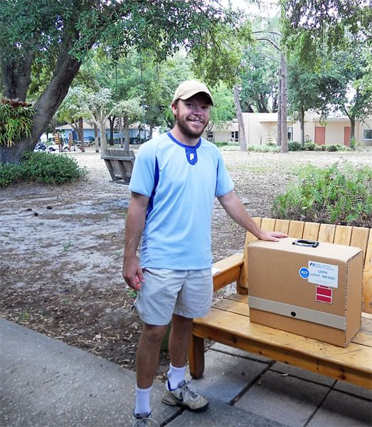
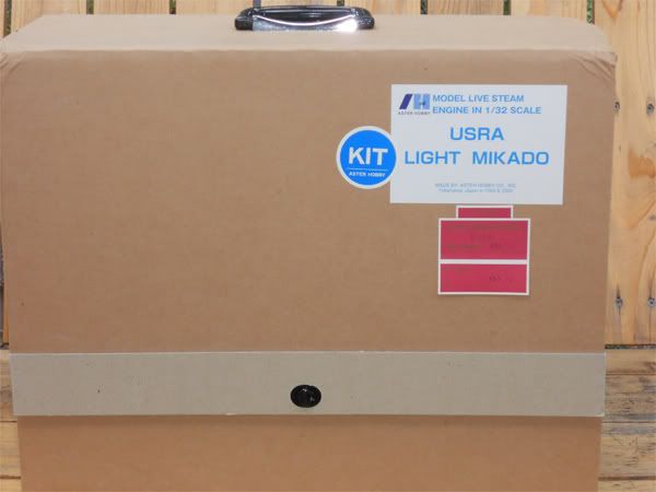
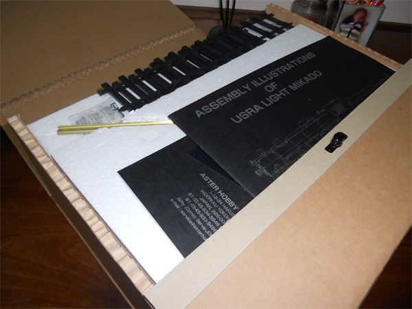
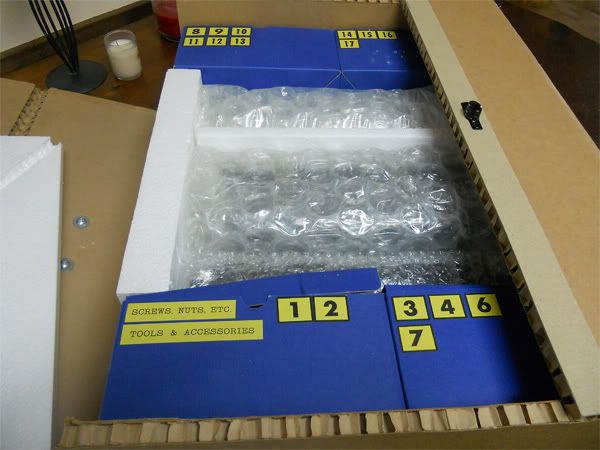
I hope all who view this can learn or enjoy the process in building a live steam engine from kit form to operational status. Here are a few photos of what I saw after taking the Aster box out of it's packing box. Lots of parts both small and large.
Subscribe to:
Posts (Atom)